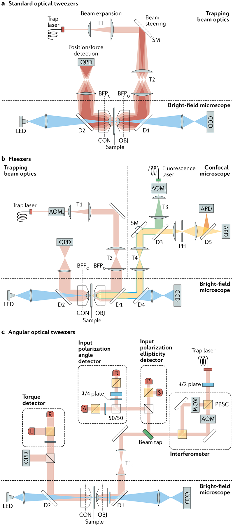
Fig. 2 |. Basic designs of optical traps.

a | Optical layout of a standard single-beam optical trap. A high-power laser generates the trapping beam (pink), which is expanded by telescope T1. Beam-steering optics (here, a steerable mirror (SM)) control the tilt in the beam axis. A high-numerical aperture objective (OBJ) focuses the trapping beam into the sample. T2 images the steering plane (at SM) onto the objective back focal plane (BFPO), so that tilting the beam displaces the trap in the sample plane. A condenser (CON) collects the light scattered by the trapped particle. A lens images the light at the condenser back focal plane (BFPC) onto a position-sensitive quadrant photodetector (QPD) for position/force detection. Two dichroic mirrors (D1 and D2) reflect the trapping beam and transmit visible light (blue) for bright-field illumination (light-emitting diode (LED)) and imaging (charge-coupled device (CCD)) of the sample plane. b | Optical layout for a representative fleezers set-up (dual traps with a confocal microscope)43. A fluorescence excitation beam (green) is expanded (T3) and directed (D3, SM, T4, D4) into the trapping OBJ. The OBJ focuses the beam to a diffraction-limited spot on the sample plane and collects light emitted within the spot. The excitation spot is displaced in the sample plane by a SM. The emitted light (yellow) travels back along the emission path, passing through a dichroic mirror (D3) and into a pinhole aperture (PH) to reject out-of-focus light. Emission light is detected by an avalanche photodiode (APD) (or by two APDs for Förster resonance energy transfer measurements). The trapping and fluorescence excitation beams are interlaced by two out-of-phase acousto-optic modulators (AOMT and AOMF, respectively). The trap layout is similar to that shown in part a, with dual traps generated by time-sharing using AOMT. c | Representative optical layout of angular optical tweezers101. The trapping laser is linearly polarized and split equally into two orthogonally polarized beams at a polarization beam splitter cube (PBSC). Each beam then passes through an AOM, and the two beams are recombined at another PBSC. Prior to the objective, the ellipticity of the laser is measured by the ‘input polarization ellipticity detector’ via photodetectors P and S, while the polarization angle is measured by the ‘input polarization angle detector’ via photodetectors A and D. After the laser interacts with a trapped cylinder in the sample plane, the transmitted laser becomes elliptically polarized, and the optical torque is measured by the ‘torque detector’ via photodetectors R and L. The force on the cylinder is measured by a QPD.
