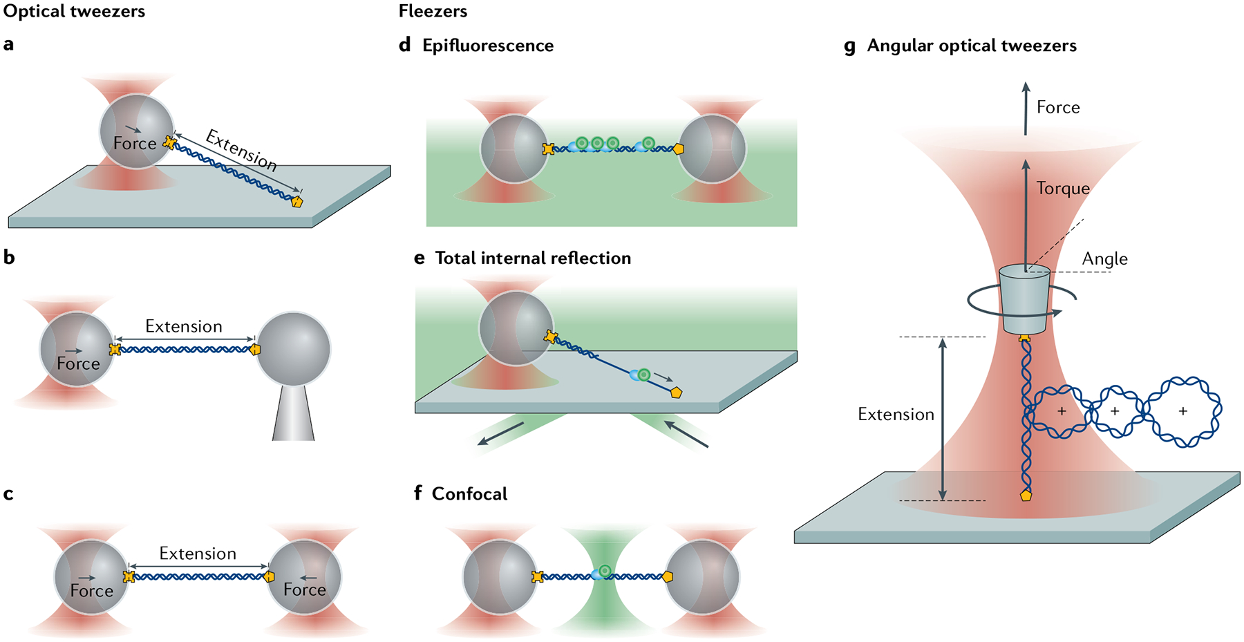
Fig. 3 |. Measurement geometries of standard optical traps, fleezers and angular optical traps.

a–c | Common optical trapping geometries11 Single-trap, surface-based geometry where a molecule (here, DNA) functionalized at both ends (yellow cross and pentagon) is tethered between a trapped bead and the sample chamber surface (part a). Single-trap, micropipette-based geometry where the molecule is attached to a trapped bead and a second bead held by suction on the end of a micropipette (part b). Dual-trap geometry where the molecule is tethered between two trapped beads (part c). d–f | Example fleezers configurations11 Dual traps with wide-field, epifluorescence microscopy, where excitation light bathes the specimen plane and fluorescence is collected from dyes (green circles) emitting in the focal plane (part d). Single trap with total internal reflection fluorescence microscopy, where excitation occurs at the chamber surface, in an exponentially decaying evanescent field (typically ~100–200 nm in depth) (part e). Dual traps with confocal fluorescence microscopy, where the excitation light is focused into a diffraction-limited spot inside the sample chamber, and only light emitted from within the spot is collected (part f). g | Basic operational geometry of angular optical tweezers (AOT)91,171. In AOT, a nanofabricated quartz cylinder is trapped. Shown is an example where the AOT are used to investigate the torsional properties of a DNA molecule by twisting the DNA. During this measurement, the AOT exert and measure torque, control rotation and supercoiling, and measure the displacement and force of the trapped cylinder, all at the same time.
