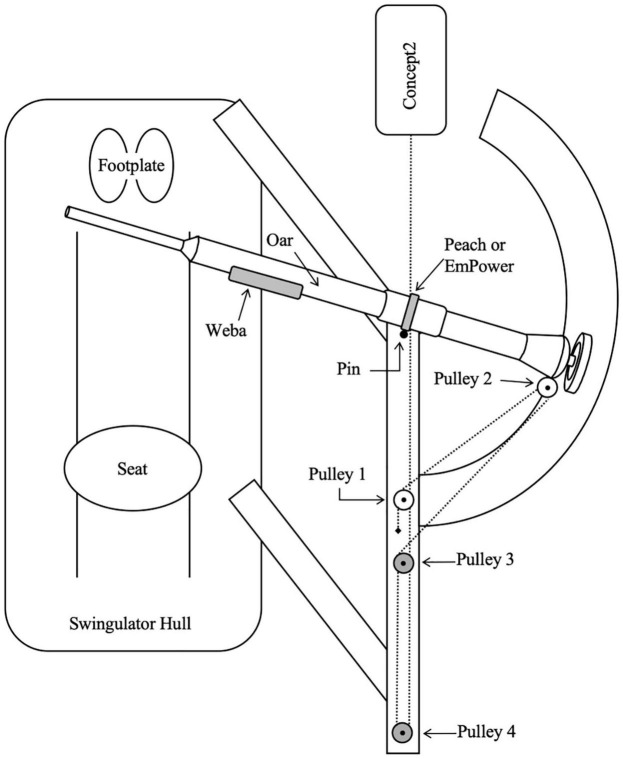
FIGURE 1.
Birds-eye view diagram (not drawn to scale) of Swingulator-system illustrating location of devices. Pin, point of oar rotation. Pulley 2 is attached to the oar, Pulleys 3 and 4 are located on the underside of the Swingulator framing. Dashed line represents the Concept2 chain and Swingulator cord which passes under the framing after Pulley 2. The black diamond near Pulley 1 indicates the anchor point of the Swingulator cord.

