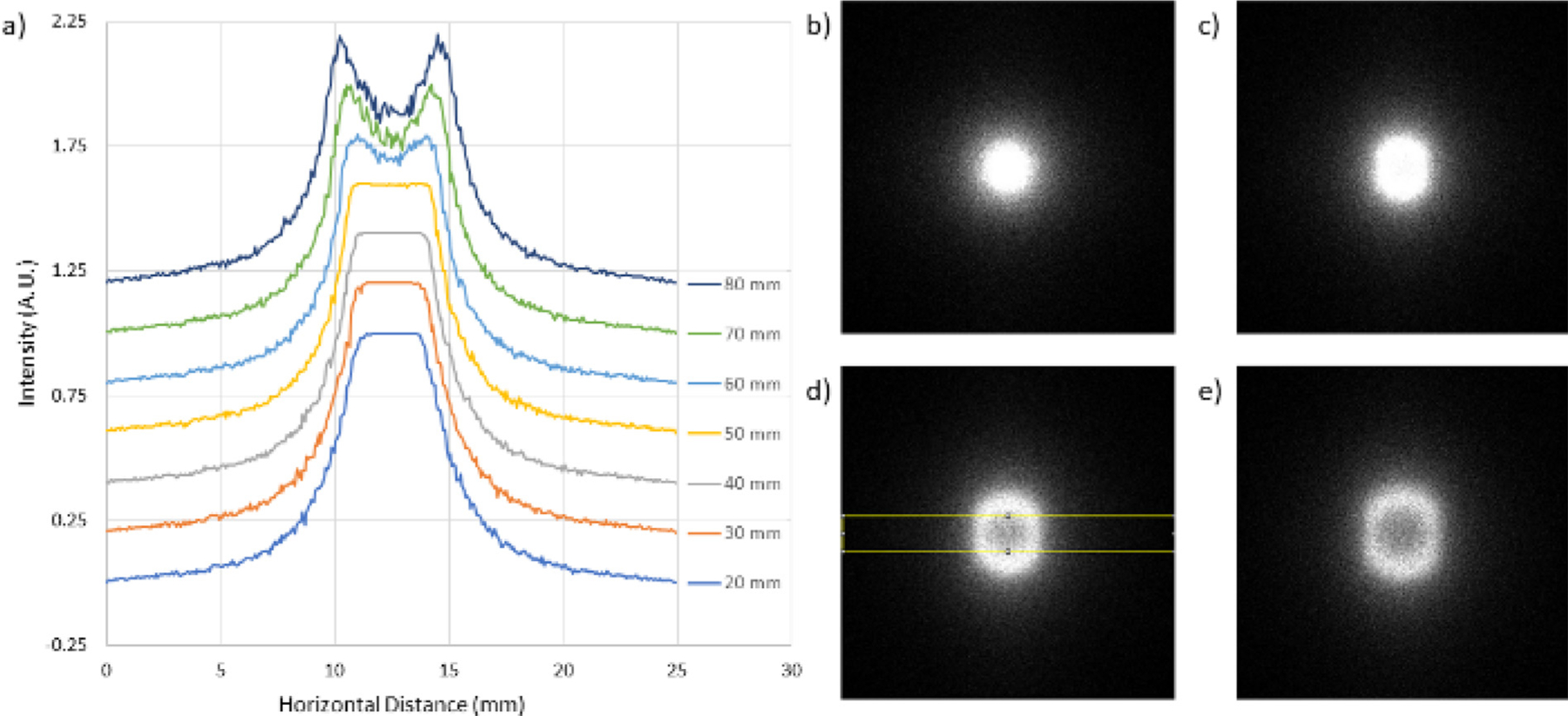
Fig. 5.

Field of view downstream of the condenser focus. (a) Horizontal line profiles of the intensity normalized to the maximum value over the region of interest shown in the yellow box in (d). The profiles have been shifted vertically for clarity. With a displacement of about 50 mm, the field of view is about 5 mm. The images (b)–(e) are the flat field for a displacement of 20 mm, 50 mm, 70 mm, and 80 mm respectively. The elongation in the vertical direction is due to the rectangular shape of the CNII.ii guide, which is 7 cm wide and 10 cm tall.
