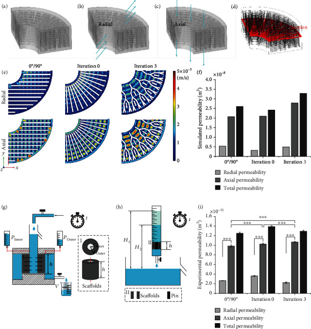
Figure 7.

Permeability of the 3D printed β-TCP/PCL scaffolds with a lay-down pattern of 0°/90°, 0 iterations, and 3 iterations. (a) Taking a quarter of the fluid computation domain obtained by the Boolean subtraction operation as the domain of interest due to the symmetry of the model. (b)-(c) Schematic diagram of radial (b) and axial (c) permeability testing. (d) Selecting a cross-section of the domain of interest to show the results of fluid flow simulation. (e) The flow rate of CFD simulations of the three porous structures. (f) Quantification of permeability simulation of the CAD scaffold models. (g)-(h) Schematic diagrams of the radial (g) and axial (h) permeability setups used to test the 3D printed scaffolds. Insets (I) and (II) are an enlarged view of the position of the scaffolds in the schematic of axial permeability tests and a top view and a longitudinal view of the scaffolds in the schematic of radial permeability tests, respectively. To prevent the liquid from passing through the central blank area of the 3D printed β-TCP/PCL scaffolds, a solid pin is placed in this area. (i) Quantification of permeability tests of the 3D printed scaffolds.
