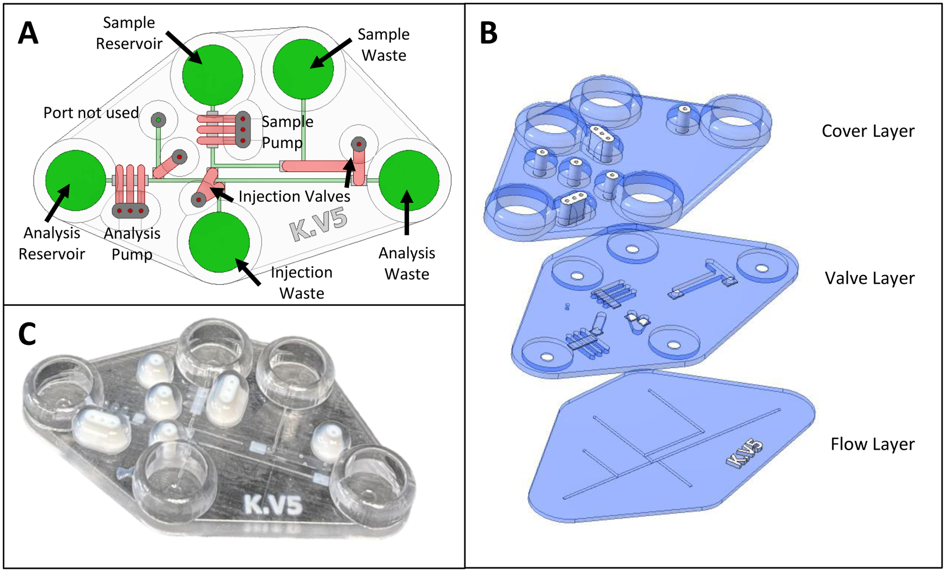
Figure 2.

CAD schematics and picture of final device. (A) Annotated CAD rendering (top-down view) of fully assembled chip, with pumps and valves in red and the flow layer in green. (B) Exploded CAD rendering showing the three layers required to fabricate the chip by support free Polyjet printing. White regions denote Agilus30 (rubber-like material) with other regions being made with VeroClear 3D printing resin. The flow (bottom) layer has the fluidic network. The valving (middle) layer contains a 280 μm thick Agilus valve (where desired) as well as the channel network to actuate those valves. The cover (top) layer has fluidic reservoirs that give access to the flow layer as well as pressure-based fittings to connect gas lines for the valves/pumps. (C) Picture of a fully fabricated chip showing the different materials that were used.
