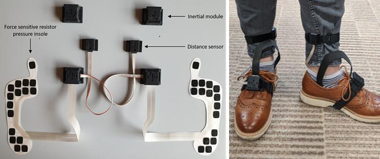
Figure 4.
Different components of the INertial module with DIstance Sensors and Pressure insoles system. The figure on the left shows the pressure insoles and the connectors that link them to the distance sensors and the inertial modules. The picture on the right shows how the same system is then attached to the participant’s foot and leg.

