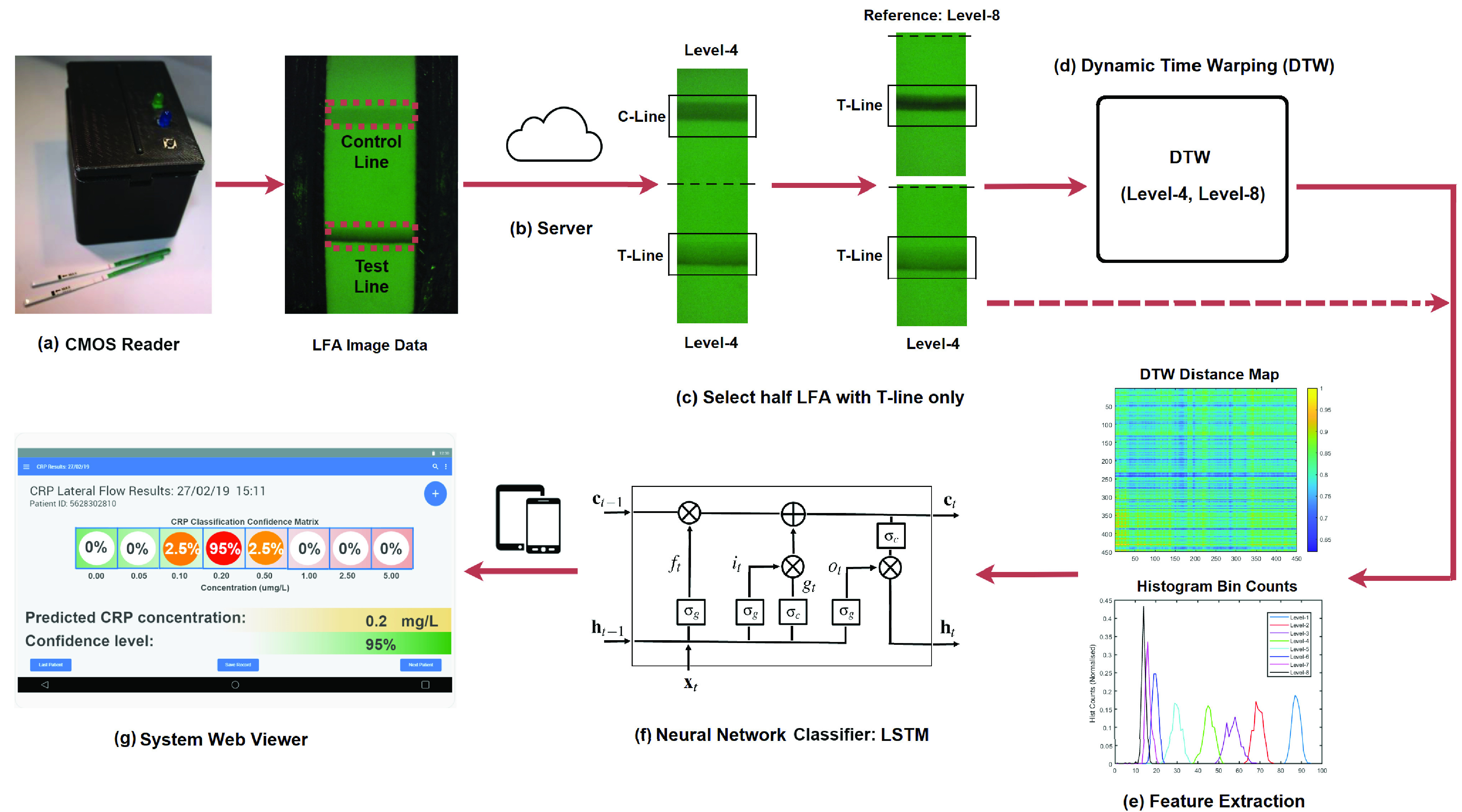
FIGURE 1.

Overview of the proposed system architecture: (a) the external view of the designed CMOS reader, in which the LFA image was taken by a CMOS camera with the control line (C-Line) and test line (T-line); (b) data were transmitted to a secured internal server for data storage, analysis and results viewer; (c) half of LFA image containing the T-line only was selected for further analysis in which the concentration level-4 was used as an example; (d) DTW was applied to level-4 LFA and a reference LFA from level-8; (e) feature extraction from DTW distance map or histogram bin counts; (f) classification via the LSTM networks; (g) a web viewer user interface where the end-users can view and query the results of classification.
