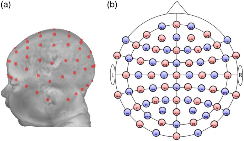
Fig. 2.

Optode and channel locations. (a) 10–10 virtual electrode placement on a 3-month individual head model. (b) A two-dimensional (2D) layout of the 10–10 systems. Sources are labeled in red, and detectors are denoted in blue. They form 130 source–detector channels.
