Fig. 1.
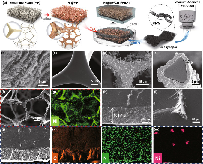
Fabrication of step-wise asymmetric Ni@MF/CNT/PBAT composites. a Schematic diagram for the preparation process of step-wise asymmetric Ni@MF/CNT/PBAT composites. b and c SEM images of CNT paper and pure MF sponge, respectively. d and e SEM images of Ni@MF-5 at different magnifications, where 5 represents the Ni-plating time of 5 min. f and g SEM of Ni@MF-5 with Ni elemental EDS mapping. h SEM image of the lower CNT-75/PBAT layer in Ni@MF-5/CNT-75/PBAT, where 75 denotes the thickness of CNT paper (μm). i SEM image of the upper Ni@MF-5/PBAT layer. j-m SEM of Ni@MF-5/CNT-75/PBAT with C, N, Ni elemental EDS mappings

