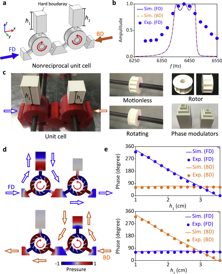
Fig. 3. Design of nonreciprocal unit cell.
a The nonreciprocal unit cell consists of two circulators with opposite rotating inner cores, viz., n1 = −n2 = 720 rpm, as marked by the red circular arrows. b The simulated and experimental (n1 = −n2 = 720 rpm) transmissions for FD (forward direction) and BD (backward direction) incidences for the unit cell with h1 = h2 = 3 cm. c Photograph of the unit cell sample, it consists of 3D printed rotors (white), cavities (red), and reconfigurable phase modulators (white). The blue and orange arrows indicate the FD and BD, respectively. The rotors are nested on carbon rods, which are driven by motors. d The acoustic pressure field distributions in the resonators at 6430 Hz for FD and BD incidences, respectively. The arrows indicate the sound propagating paths. e The simulated (Sim.) and experimental (Exp.) phase responses at 6430 Hz for FD and BD, by independently changing the parameters of h1 and h2, respectively.

