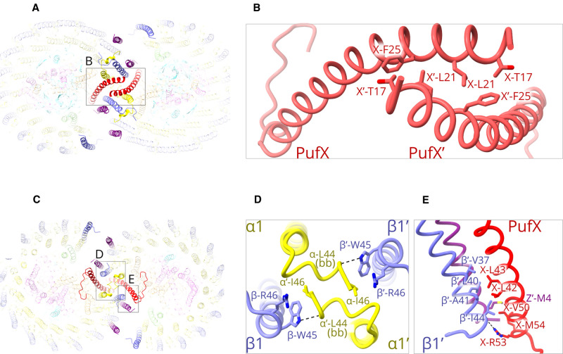
Figure 3. Protein–protein interactions at the dimer interface.
(A) View of the cytoplasmic side of the dimer. For clarity, all components are faded except for those at the interface. (B) Detailed view of the region indicated by the box in (A) showing PufX and PufX’ interacting near their N-termini on the cytoplasmic side of the membrane, with important sidechains labelled. (C) View of the periplasmic side of the dimer, with other features as in (A). (D) Detailed view of the region indicated by the left-hand box in (C), and rotated by 90°, showing C-terminal interactions between opposing LH1 α, α′ and β, β′ subunits at positions 1 and 1′ (see Figure 1B for numbering). Dashed lines indicate hydrogen bonds, which are 3.3 Å (see also Supplementary Table S2). (E) The components shown in the right-hand box in (C), but viewed from a different angle, showing C-terminal interactions between PufX on one side of the dimer complex, and protein-Z′ and the LH1 β′ subunit at position 1′ on the other side. The hydrogen bond between X-Arg53 and β1′-Ile44 is 2.8 Å (see also Supplementary Table S2).

