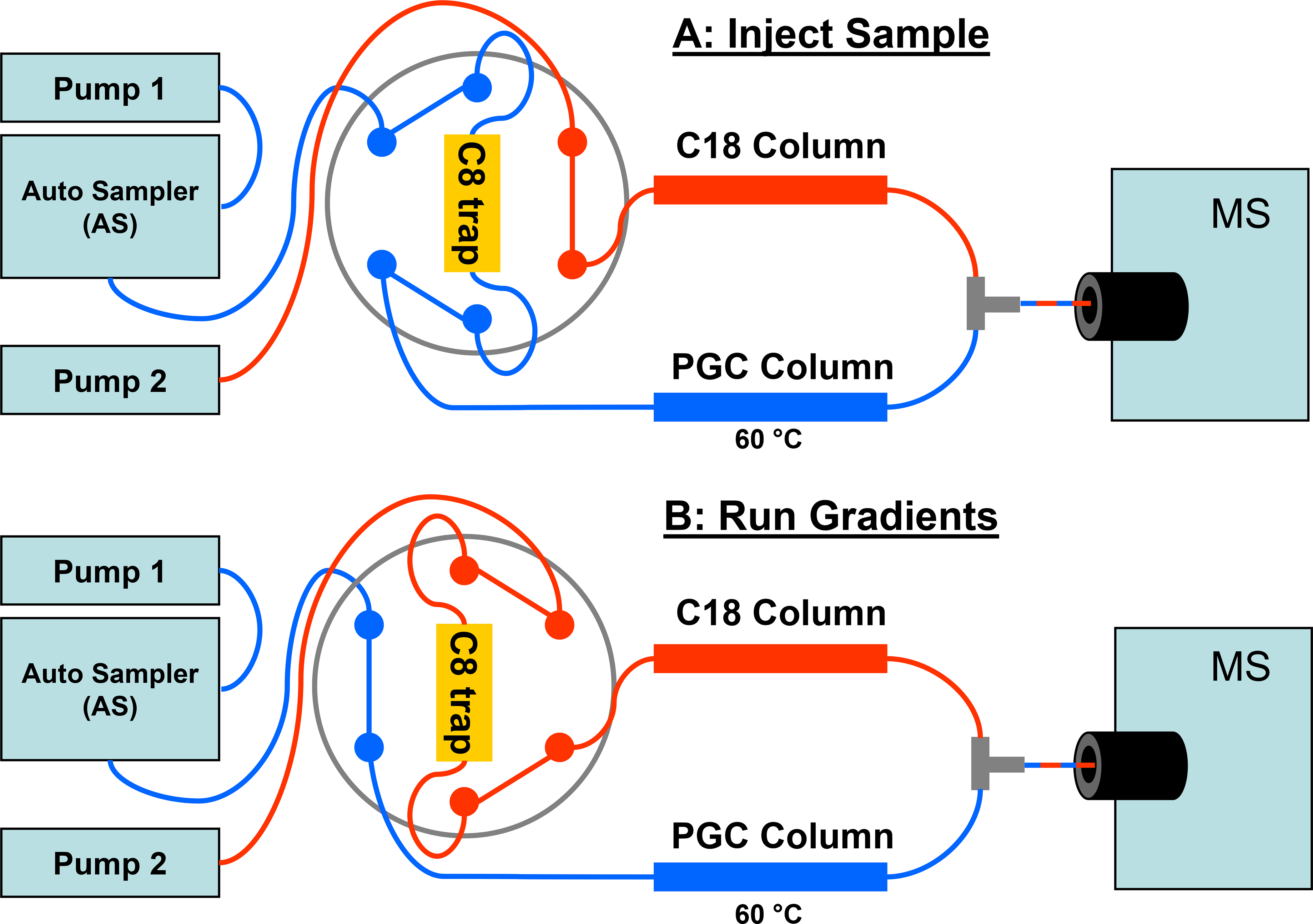
Figure 1.

Schematic and operation of the total retention LC-MS system. (A) Shows the flow path when a sample is injected. Flow from pump 1 (in blue) carries the sample aliquot from the autosampler, to the C8 trap and onto the PGC column. During this period, flow from pump 2 (in red) goes only to the C18 column. (B) Shows the flow path during the analytical gradients for the C18 and PGC columns where the 6-port valve has been actuated to the alternate position. Flow from pump 2 (in red) now passes through the C8 trap and onto the C18 column. Flow from pump 1 (in blue) goes directly to the PGC column. The PGC and C18 columns are connected to a tee prior to the MS.
