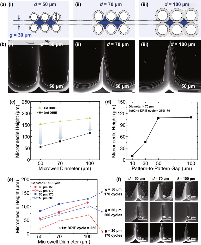
Fig. 4.
Effects of the design parameters and cycles of isotropic etching on final microneedle structure. a Illustration of photomask designs with a fixed gap (g) of 30 μm and microwell diameters (d) of 50, 70, and 100 μm. Solid and dashed circles indicate initial microwell patterns after the anisotropic DRIE and widened areas during the isotropic DRIE, respectively. Blue polygons represent Si areas to be microneedles. b SEM images showing cross-sectional views of microneedles created from the three microwell diameters. c Microneedle heights as a function of different microwell diameters after the 1st and the 2nd DRIEs. d Microneedle heights as a function of pattern-to-pattern gap. e Microneedle heights as function of microwell diameters for several combinations of pattern-to-pattern gap and number of the 2nd DRIE cycles. f SEM images of microneedles fabricated from the three conditions described in panel e. Note that, scale bars are different in each SEM image

