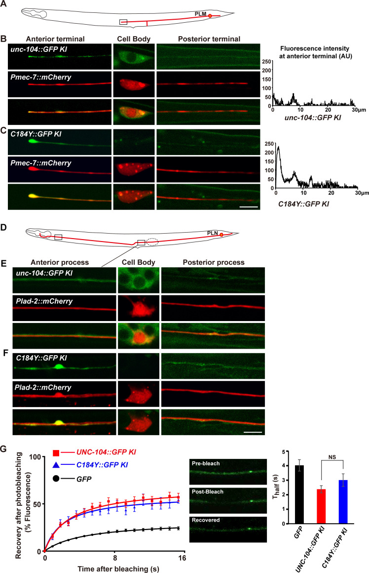
Fig 5. The UNC-104C184Y motors accumulate on neuronal processes of PLM and PLN neurons.
(A) The schematic drawing illustrates the PLM neuron (red) in C. elegans. Boxed region indicates the terminal region of the anterior process of PLM. (B) The UNC-104::GFP distribution in PLM neuron. The PLM neuron is in red. The UNC-104::GFP is in green. (C) The UNC-104C184Y::GFP distribution in PLM neuron. The PLM neuron is in red. The UNC-104C184Y::GFP is in green. Scale bar represents 5 μm. (D) The schematic drawing illustrates the PLN neuron (red) in C. elegans. (E) The UNC-104::GFP (green) is diffusely distributed in PLN neuron (red). (F) The UNC-104184Y::GFP (green) is accumulated on the neuronal process of PLN neuron (red), particularly in the two regions indicated by solid boxes. Scale bar represents 5 μm. (G) The FRAP analysis was conducted in the region encircled by dashed line. Curves of fluorescence after photobleaching of wild type UNC-104::GFP and UNC-104C184Y::GFP on PLN neuron. N = 28 for wild type UNC-104::GFP and N = 24 for UNC-104 C184Y::GFP.

