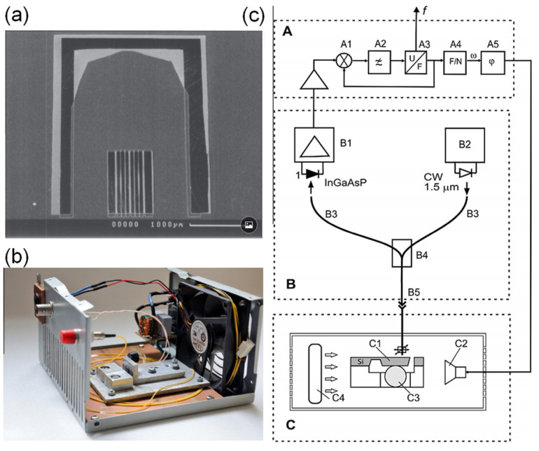
Figure 21.
Point sensor. (a) SEM image of the sensor head. (b) Photograph of the sensing system. (c) Experimental setup: A—unit for phase lock: A1—synchronous detector with analog switches, A2—low pass filter, A3—voltage-controlled oscillator, A4—frequency divider, and A5—phase-shift module; B—optical part: B1—photodetector, B2—laser module, B3—optical fiber, B4–fiber coupler, and B5—optical connector; and C—sensitive element: C1—mechanical resonator, C2—miniature loudspeaker, C3—silica gel granule, and C4—mini-fan. Adapted with permission from ref. [98]. Copyright 2014 Elsevier.

