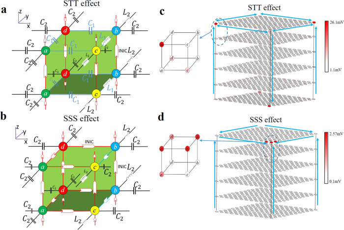
Fig. 5. The circuit design and results for the hybrid 3D skin-topological-topological (STT) effect and 3D skin-skin-skin (SSS) corner effect.
a, b The schematic diagrams for the unit cell of the total circuit with C1 = 1 nF, L1 = 3.3 uH, C2 = 2.2 nF and L2 = 1.5 uH. Arrows with different colors are the same as INICs labeled in Fig. 1d. Each unit cell contains four sublattices (a, b, c, d). a is for hybrid 3D STT effect and b is for 3D SSS effect. The details of INICs are in Fig.1d. c, d The voltage distributions at the resonance frequency for hybrid 3D STT effect and 3D SSS effect in (c) and (d), respectively. Big arrows in (c) show the directions of skin and topological pumping. Big arrows in (d) show the directions of skin pumping.

