Fig. 5.
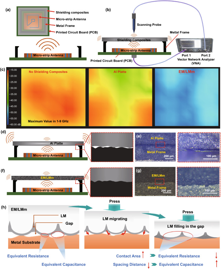
NF-SE performance of EM/LMm and the comparison of EM/LMm with other LM and shielding materials. a, b Schematic depicting the NF-SE testing principle and system. This testing model is mainly to measure the near field EMI SE performance of shielding materials by testing the relative electric and magnetic signals. c NF-SE mapping images of bare antenna, shielding with Al plate and shielding with EM/LMm (maximum value in every point among 1–9 GHz). d, e Schematic of shielding model with Al plate, and the optical images of the interface between the metal frame and Al plate. The holes were caused by the hard surface of the metal frame and Al plate. f, g Schematic of shielding model with EM/LMm. The optical images between the metal frame and EM/LMm show a tight interface. h The schematic diagram of interface electromagnetic self-sealing mechanism of EM/LMm

