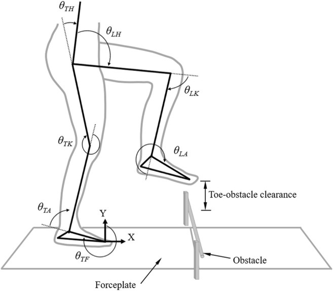
FIGURE 2.

The planar seven-link model of the body when obstacle-crossing. Two forceplates are placed on either side of the obstacle. Definitions of the toe-obstacle clearance and the joint angles are also indicated: hip ( ), knee ( ) and ankle ( ) of the leading swing limb, and foot ( ), ankle ( ), knee ( ) and hip ( ) of the trailing stance limb. The upper body, namely the segments of the head/neck, trunk, pelvis, and upper extremities, was modeled as a single link, defined as the line connecting the hip joint center and the center of mass of all the upper body segments. The hip angles were defined as the angles between the upper body link and the thigh links. The X-axis indicates the direction of progression.
