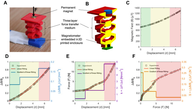
Figure 2.
Magnetic-based transduction method of the MST Sensor. (A) A single three-layer block with integrated permanent magnet as stimulus, and magnetometer covered by a 3D printed holder. (B) Schematic cross-section of the single block. (C) The variation of the overall magnetic field with respect to the displacement of the permanent magnet in the top layer. (D) The variation of the with respect to the permanent magnet displacement (left y-axis), linear fitting (red lines) at three locking stages (highlighted background in green, yellow, and red), and gradient of linear fitting (right y-axis) corresponding to . (E) The variation of the applied force with respect to the displacement of top layer (left y-axis) linear fitting (red lines) at three locking stages, and gradient of linear fitting (right y-axis), corresponding to the stiffness of different layers of the block (). (F) The variation of the with respect to the applied force (left y-axis), linear fitting (red lines) at three locking stages, and gradient of linear fitting (right y-axis), corresponding to the multiple sensitivities of the MST sensor at different force sensing ranges ().

