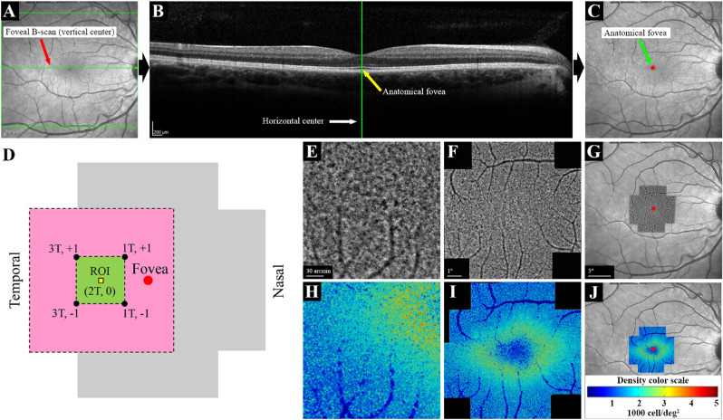
Figure 1.
Procedures used for image acquisition, montage and marking the foveal center in a normal eye. Vertical (A) and horizontal (B) centers of the high-resolution IR image were located using the HEYEX software, and the foveal center was marked on the IR image (C). The AO imaging protocol included 12 overlapping 4° × 4° image frames covering the central 10° (D). Fovea, region of interest (ROI), and x, y coordinates (degrees from the fovea) of the four overlapping image frames are shown. The pink area (6° × 6°) shows the area covered by the four overlapping image frames, and the green area (2° × 2°) shows the area shared by these image frames. The ROI (80 µm × 80 µm) was located on the horizontal meridian, 2° temporal to the fovea. Individual AO image frames (E) were stitched together to create an AO montage (F). The AO montage was overlaid on the center-marked IR image, and the foveal center was marked on the AO montage (G). The same procedure was performed for the analyzed AO images to create cone density maps (H–J). The color code for the density map is shown in (J). T, temporal; +, superior; −, inferior.

