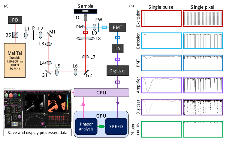
Fig. 1.
Fast fluorescence lifetime imaging microscopy (FLIM) setup with analog output photomultiplier tube (PMT) and graphics processing unit (GPU) accelerated computational photon counting. (a) Optical microscopy and acquisition system diagram including two-photon excitation from a tunable fs laser, laser scanning with galvanometer mirrors, a dichroic mirror to direct emitted fluorescence through a filter wheel (FW) to the PMT. The PMT output is amplified with a transimpedance amplifier (TA) and digitized. The digitized data is copied to the GPU for accelerated computational photon counting via single-photon peak event detection (SPEED) and determination of intensity, phasor components, and mean lifetime for each pixel, which are copied back to the central processing unit (CPU) and displayed in real-time. (b) Signals represented on normalized scales of intensity vs. time in various locations from (a), indicated by the colored boxes. Raw data from a sample of urea crystals is shown in the “Digitizer” column; the signals displayed in the four preceding boxes are estimations based on the digitized data and the “Photon counts” were computed using SPEED. Single pulse (12.5 ns) and single pixel (625 ns) signals are given in the left and right columns, respectively. BS, beam splitter; PD, photodiode; L, lens; P, pinhole; M, mirror; G, galvanometer scanning mirror, G; DM, dichroic mirror; OL, objective lens.

