Fig. 1.

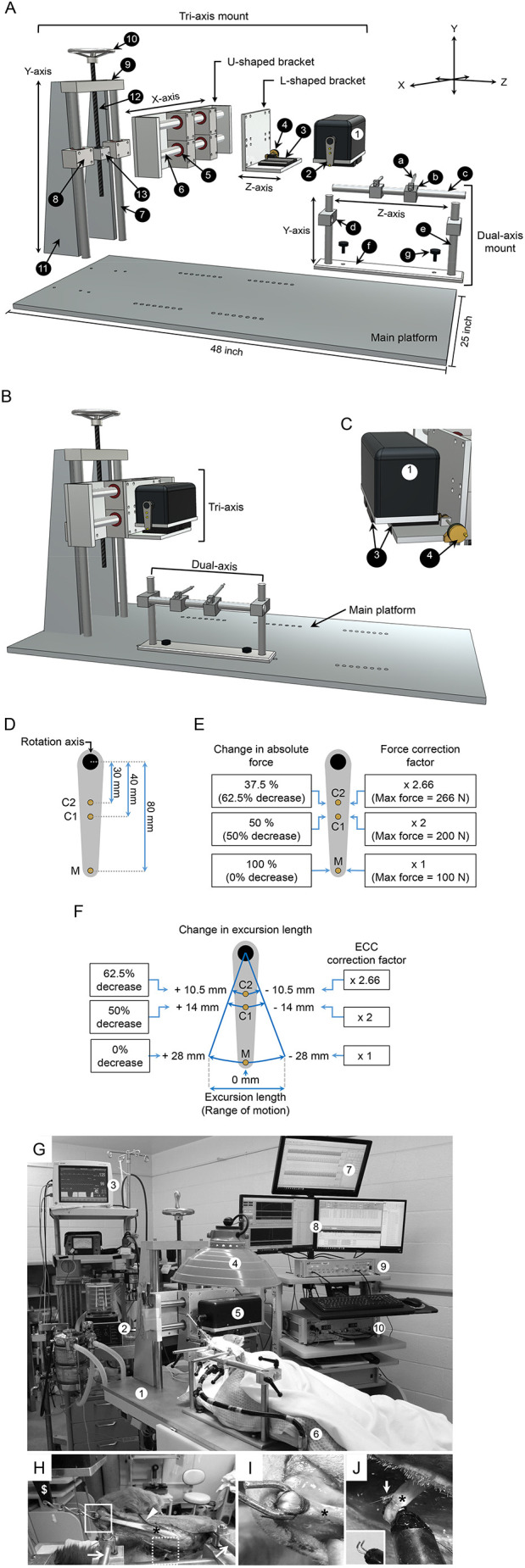
Muscle force assay system. (A) A diagrammatic drawing of the disassembled force assay platform. The custom-made muscle force assay platform has three components: a main platform, a tri-axis mount and a dual-axis mount. The numerical number in the tri-axis mount refers to (1) force transducer, (2) lever arm, (3) translational stage, (4) translational knob, (5) linear horizontal bushing, (6) horizontal stainless-steel rod, (7) vertical stainless-steel column, (8) linear vertical bushing, (9) horizontal aluminum plate, (10) adjustment screw with a wheel knob, (11) vertical quadrilateral support plate, (12) threaded steel rod and (13) aluminum mounting adaptor. The small letters in the dual-axis mount refer to (a) bone pin, (b) stainless-steel mount for the bone pin, (c) x-axis stainless-steel rod, (d) stainless steel mount module for the x-axis stainless-steel rod, (e) vertical stainless-steel rod, (f) bottom plate to attach the dual-axis mount to the main platform and (g) stainless steel screw. (B) A diagrammatic drawing of the assembled force assay platform. (C) A diagrammatic drawing of the L-shaped bracket, force transducer, translational stage and translational knob. The movement of the force transducer on the x-axis is regulated by the translation stage and the translation knob. The numbers refer to the same components shown in A. (D) A schematic of the three muscle attachment sites on the lever arm. M refers to the site made by the manufacturer. C1 and C2 refer to the customer engineered sites 1 and 2, respectively. The distance between the center of the rotation axis and the muscle attachment site are marked. (E) The maximum resistant force at each muscle attachment site and the force correction factor. The maximum resistant force at the M, C1 and C2 sites is 100 N, 200 N and 266 N, respectively. The correction factor for the M, C1and C2 sites is 1, 2 and 2.66, respectively. (F) The excursion length at each muscle attachment site and the length correction factor for eccentric contraction (ECC). The excursion length at the M, C1 and C2 sites is ±28 mm, ±14 mm and ±10.5 mm, respectively. (G) A photo of the experiment setting. The numbers refer to (1) the force assay platform, (2) ventilator, (3) vital signs monitor, (4) heat lamp, (5) force transducer, (6) conductive warming blanket, (7) LabChart software for tracing arterial blood pressure and blood flow, (8) Dynamic Muscle Control software, (9) stimulator and (10) force transducer controller module. (H) A photo showing the mounting of the forelimb on the dual-axis mount using the bone pins (arrow). The ECU muscle (asterisk) was surgically exposed and attached at the distal tendon to the force transduce lever arm (dollar sign) through a stainless chain (boxed region). The temperature probe (arrowhead) was placed behind the ECU muscle to monitor the muscle temperature throughout the experiment. The radial nerve was exposed for electric stimulation (dotted boxed region). (I) A closer view of the boxed region in H showing the attachment of the stainless-steel chain to the distal tendon (asterisk) of the ECU muscle. (J) A closer view of the dotted boxed region in H showing the attachment of the radial nerve (asterisk) to the electrode (arrow). The inset shows the electrode without the attached nerve.
