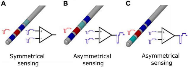
FIGURE 1.

Differential sensing configurations for conventional DBS electrode. (A) Symmetrical sensing employs two recording contacts (blue) adjacent to the stimulation contact (red); at the inputs of the differential amplifier, the common mode stimulation artifact (in the ideal case of balanced impedances) is the same, and for an ideal common mode rejection ratio (CMMR), the output of the stimulation artifact is canceled by subtraction. (B) Asymmetrical sensing employs two recording contacts (blue) in the opposite position but at different distance compared to the stimulation contact (red), or two recording contacts (blue) in the same position and at different distance compared to the stimulation contact (red). At the inputs of the differential amplifier, the common mode stimulation artifacts (in the ideal case of balanced impedances) are not the same; even for an ideal CMMR, the output of the stimulation artifact is not canceled by subtraction. In real case scenario, impedances are unbalanced and the CMMR is not ideal; therefore, asymmetrical sensing implies a further worsening of the recording configuration. (C) Asymmetrical sensing with two adjacent contacts. The panel is organized as in (B) and the same comments apply.
