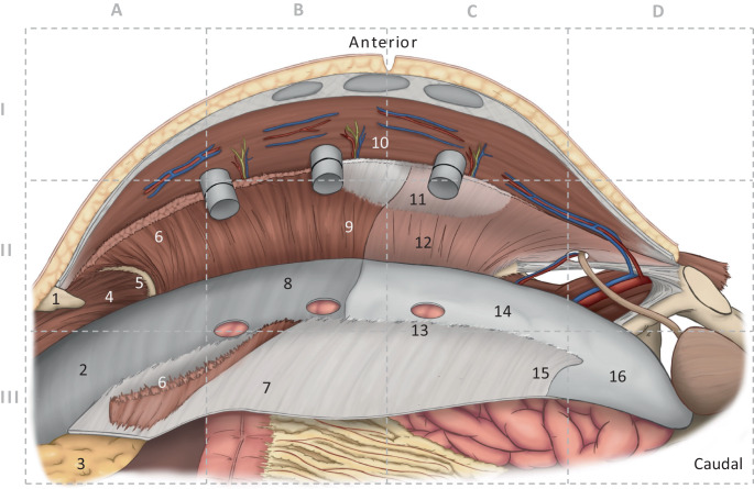
Fig. 1.
Anatomy of the robotic transversus abdominis release (r-TAR). Intraoperative view of the left side of the abdominal wall; the right (contralateral) side was previously prepared over the three visible trocars (12, 8, and 8 mm). The grid is used as a guide in Figs. 2 and 3. Anatomical structures: 1 xiphoid, 2 fascia diaphragmatica, 3 retroxiphoidal-preperitoneal fat (fatty triangle), 4 diaphragm, 5 costal arch margin, 6 detached transversus abdominis in the area of its insertion onto the posterior rectus sheath, 7 posterior rectus sheath, 8 endoabdominal fascia with peritoneum, 9 transversus abdominis cleared from its fascia (typical preparation layer in the cranial region), 10 intercostal nerves, 11 linea semilunaris, 12 transversus abdominis with its fascia (typical preparation layer in the caudal region), 13 port hole, 14 peritoneum, 15 arcuate line, 16 preperitoneal region in the retropubic space

