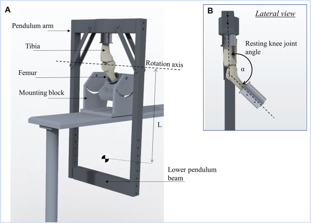
FIGURE 3.
Schematic representation of the passive pendulum friction testing device that was used (A). The femur is fixed in an inclined mounting block and the pendulum arm is attached to the tibia, whereby the resting knee joint angle between the tibia and femur (α) was set to 140° to achieve a physiological joint loading (B). The rotation axis of the pendulum motion is described by the rotation axis of the knee joint in flexion-extension. The length of the pendulum (L) is the distance from its center of mass to the rotation axis.

