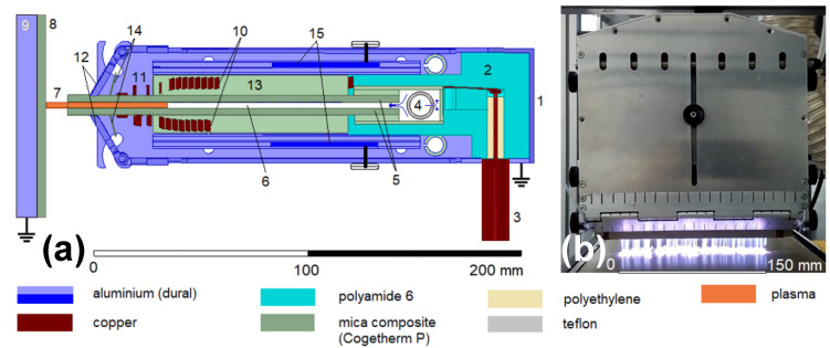
Figure 1.
(a) Schematic drawing of the RF plasma slit jet (side view): 1—aluminum cover/shielding; 2—load-bearing element; 3—coaxial cable; 4—Ar flow homogenization region; 5—mica composite slit body; 6—slit; 7—plasma region; 8—sample; 9—grounded metal desk; 10—resonance coil; 11—high-voltage radio-frequency electrodes; 12—system of movable grounded electrodes; 13—dielectric plates of an electrical breakdown limiter; 14—plates supporting the coil turns; 15—conductive plates of resonance matching circuit. (b) Front view of RF plasma slit jet running in pure Ar with a mica composite sheet as a substrate.

