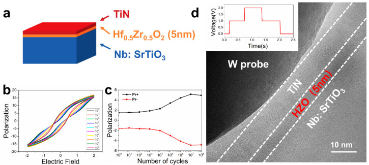
Figure 5.
The Hf0.5Zr0.5O2 (HZO) thin film for in situ electrical experiments. (a) Schematic diagram of the HZO-based ferroelectric thin film capacitance structure for experiment. (b) Typical P–V curves of HZO(5nm) capacitor. (c) The tendency of Pr to cycles under 2.5 V. (d) High resolution TEM (HRTEM) image shows the in situ biasing process for a local area in the HZO thin film with the aid of tungsten probe.

