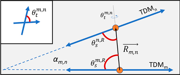
Figure 5.

Diagram depicting relative orientation parameters for a pair of TDMs in an H-like stacking arrangement, including oblique angle, α, the center-to-center separation vector, R, the relative slip angles, θs, and the twist angle, θt (see section S3). Note that, here, α is shown in two dimensions for the special case of zero twist angle, but in general the angle spans three dimensions. The inset shows the twist angle looking along the separation vector from m to n. The slip angle for nonparallel TDMs will depend on which TDM is chosen as the reference.
