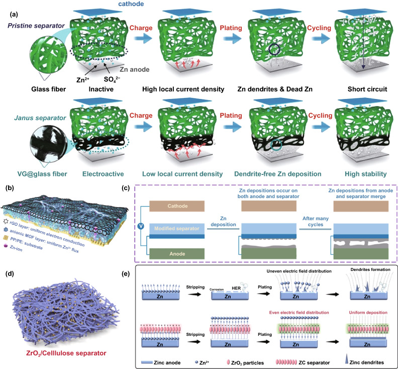
Fig. 25.
a Schematics illustrating (top) a pristine glass fiber separator and (bottom) a Janus separator targeting stabilized Zn anode [174].
Copyright 2020, Wiley–VCH. b Schematic illustration for the Janus separator [175]. c Schematic illustration of Zn deposition in the contact region of the modified separator and the anode [176]. d Schematic illustration for the ZC separator; e Schematic illustration of possible migration process of Zn2+ when passing through the cellulose and ZC separators [177]. Copyright 2021, Elsevier

