
Figure 3.
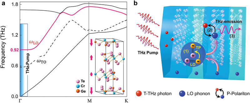
Schematic of phonon‐polariton generating THz radiation scheme. a) Sketched phonon dispersion of Cr2Ge2Te6 crystal corresponding to the THz radiation. The THz radiation involved zone‐folded LO layer‐breathing mode is depicted with red curve. The black dashed curve is the inter‐layered transverse optical (TO) phonon mode. The shaded region exhibits the spectral range of incident THz pump. Inset shows the crystal structure of the Cr2Ge2Te6 crystal, in which these red arrows indicate the oscillation directions of the inter‐layered breathing mode. b) Diagram of the coupling of LO layer‐breathing mode and THz photons, resulting in the formation of P‐Polaritons and ensuing monochromatic THz EM emission. The inset marked with a pink arrow illustrates the intermediate (TP) during the whole process. The formation processes of TP, P‐Polariton, and THz emission correspond to (1), (2), and (3), respectively.