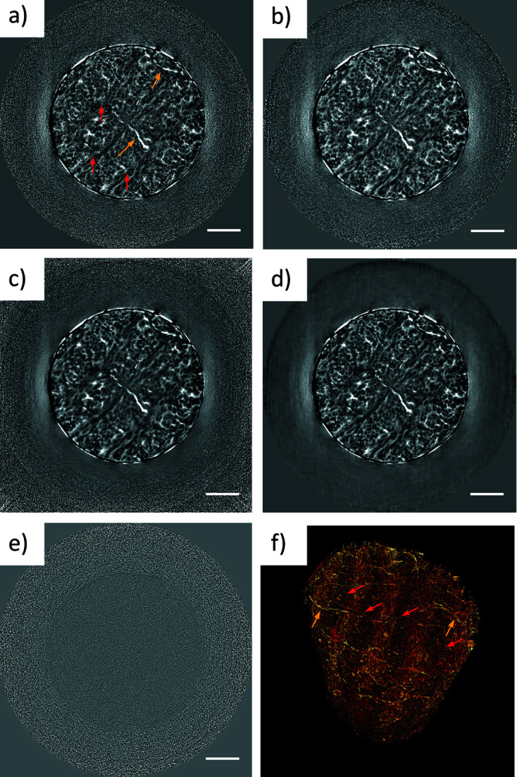
Figure 8.

Denoising of a bone sample, showing (a) a slice of the unfiltered reconstruction, (b) a slice filtered with the median 3D filter and (c) the NLM filter. (d) The denoised slice performed using a network trained on a different structurally similar sample. (e) Difference image of the unfiltered image (a) and the ML denoised image (d). (f) Volume rendering of the bone, achieved by thresholding the ML-denoised tomogram. Red arrows point to the lamellae and yellow arrows indicate the positions of the canaliculi. The scale bars are 5 µm.
