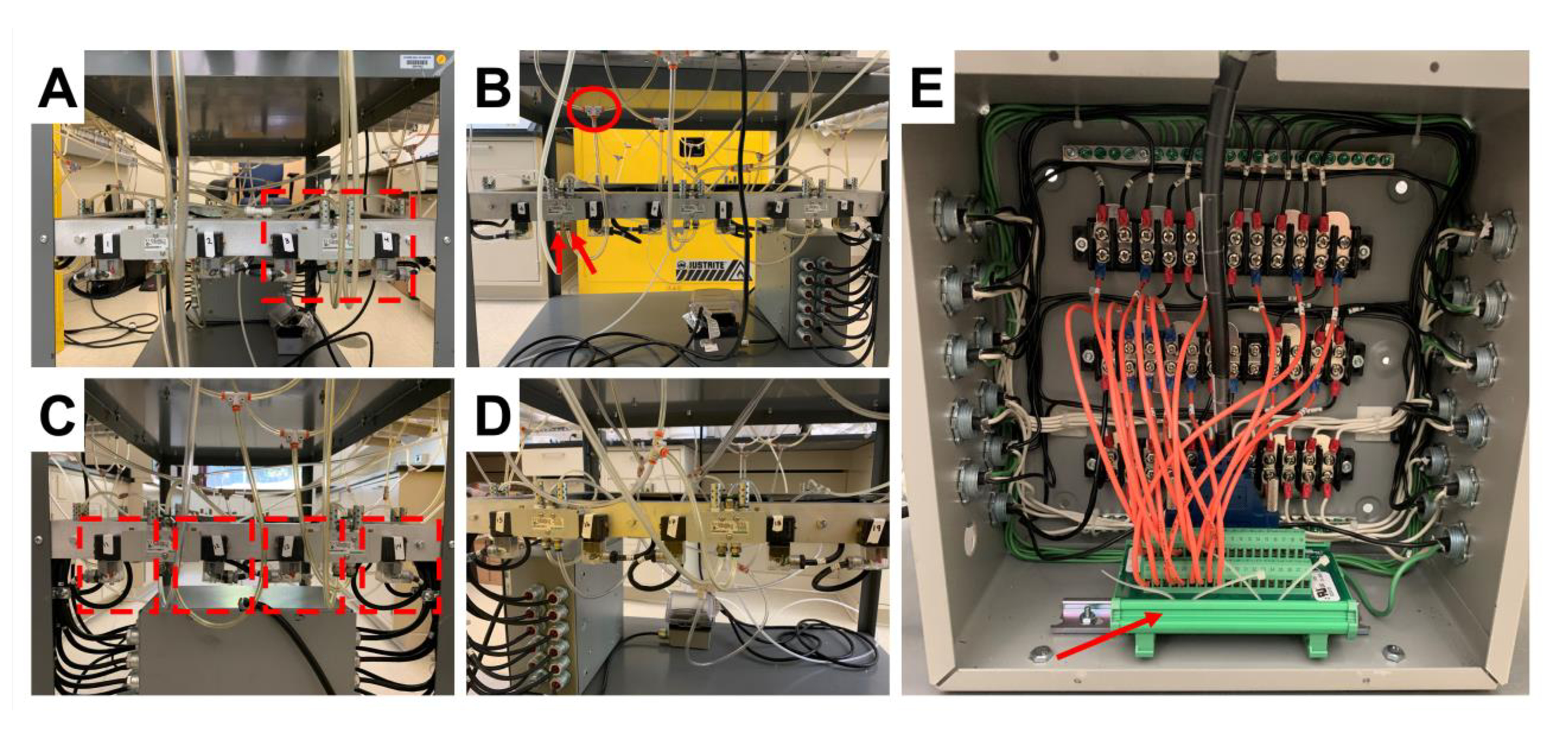
Figure 1. Electronics and valve system of the braiding machine.

A-D) Demonstrates the air valves in sequential order, from all four sides of the braiding machine, that control the motion of the pistons. A) Highlights an air valve. B) Highlights the outlet port of the air valve (red arrows), and the tee splitter that directs air to the air cylinders (red circle). C) Highlights a modified extension cord (red outline) which provides the electrical signal to control the air valve. E) Demonstrates the control panel of the braiding machine and the high voltage terminal (red arrow) that is connected to a computer via a D-sub cable.
