
Figure 3. Components of the ATUM and path of the tape through the ATUM.
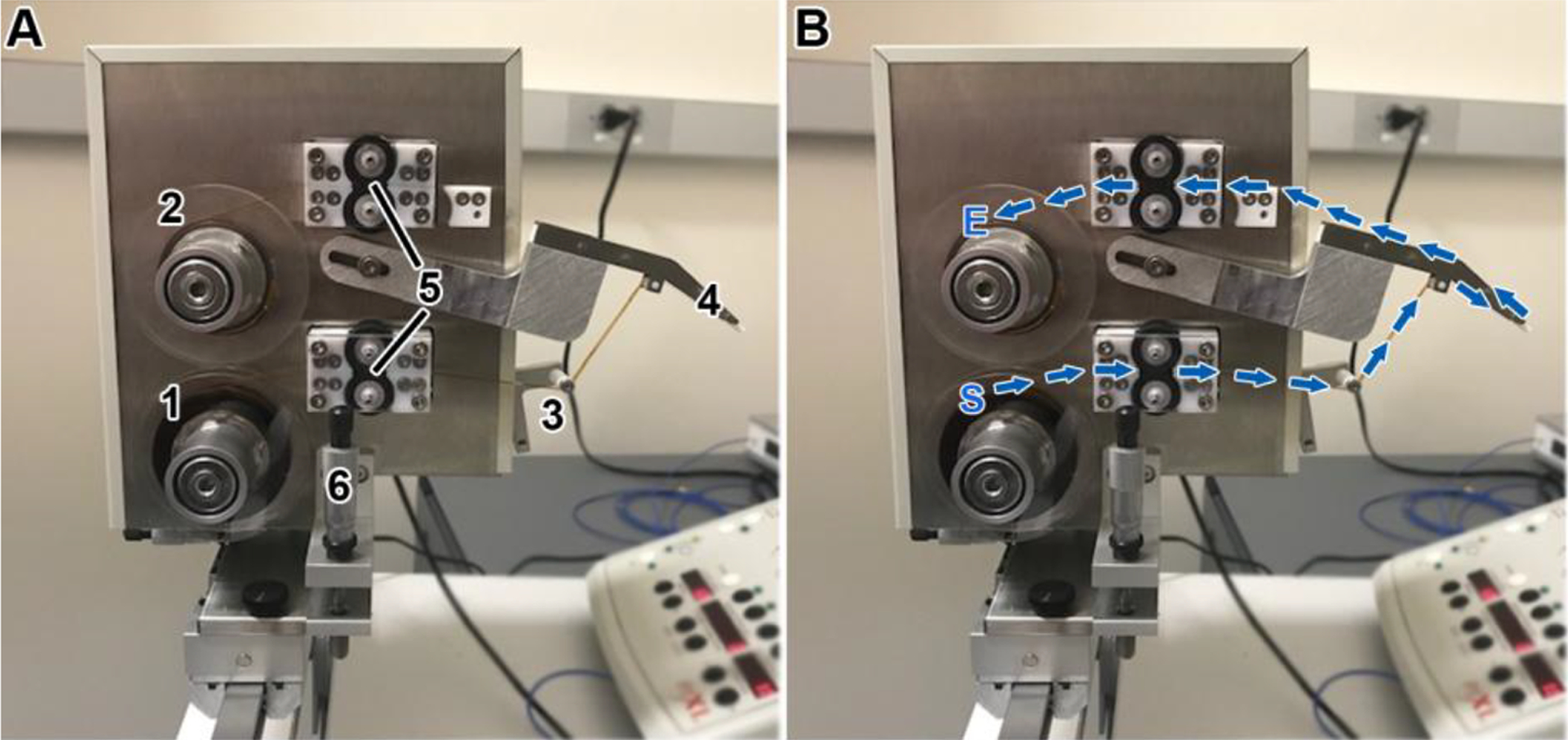
(A) Picture of the ATUM indicating its main components. (1) supply reel for the tape, (2) a take-up reel, (3) tape tensioner, (4) snout, (5) bottom and top pinch rollers, and (6) Z-height control. (B) The path of the tape begins at the supply reel (S), goes through the bottom pinch rollers (set in the “on” position), around the tensioner arm roller, around the snout, through the top pinch rollers, and ends at the take-up reel (E) to which it is attached with adhesive tape.