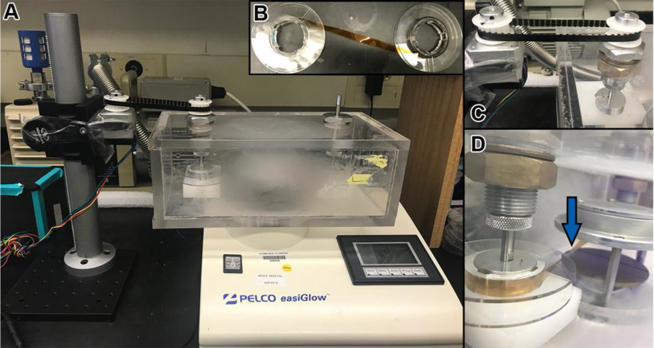
Figure 5. Glow discharge system for tape.

(A) Picture showing the PELCO easiGlow discharge unit (Ted Pella, Inc.) with a custom-made chamber. Within the chamber, the tape is passed from a source reel, through the glow discharge area, and is then collected on a take-up reel. The take-up reel is turned by a motor and a belt system (left). (B) Before placing the tape in the chamber, it is attached from the source reel to the take-up reel with adhesive tape. (C) Motor and belt system for turning reels with tape. (D) One of the reels is turned accordingly so that the tape runs parallel to the discharge plates and the underside of the tape (the side which will collect the sections) faces up as it runs in between the plates (blue arrow).
