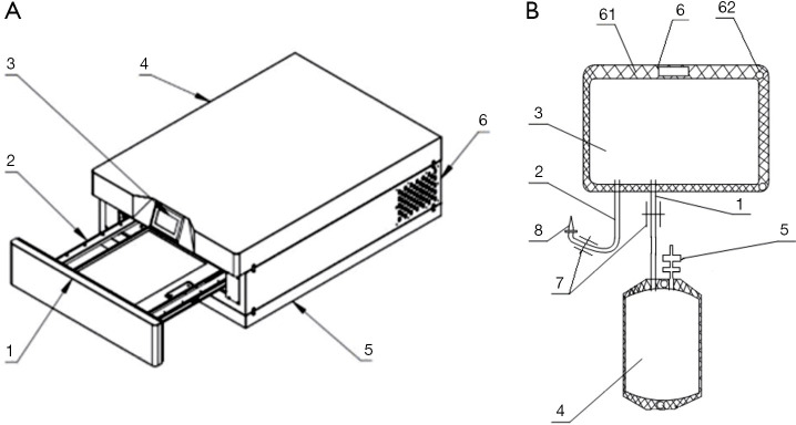
Figure 1.
Schematic diagram of the inactivating instrument and blood bag. (A) Inactivating instrument: [1] cabin door, [2] tray, [3] display, [4] cabinet, [5] base, and [6] air outlet. (B) Blood bag: [1] connecting tube, [2] injection tube, [3] light treatment bag, [4] platelet storage bag, [5] blood transfusion port, [6] fixing part, [61] cardboard, [62] through hole, [7] check valve [8], and puncture needle.

