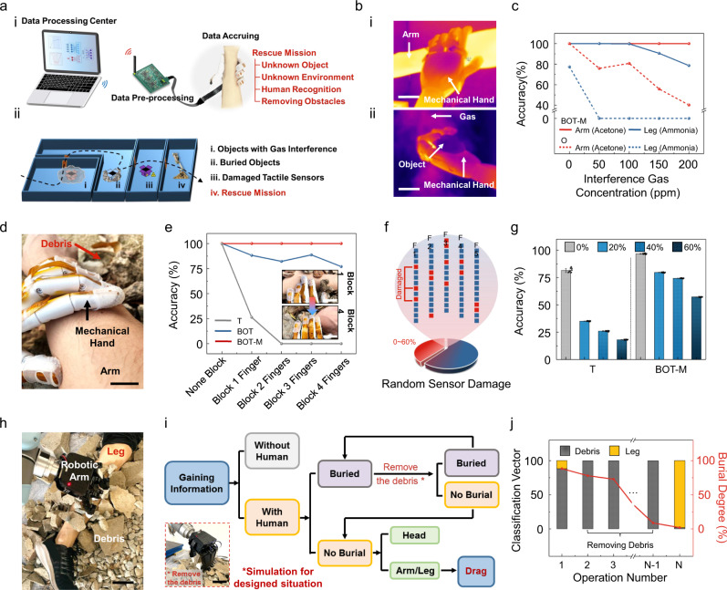
Fig. 4. Human recognition in a hazardous environment based on BOT.
a Schematic illustration of the testing system and scenarios. (i) Scheme showing the system consisting of a computer, a wireless data transmission module, a data pre-processing circuit board, and a mechanical hand. (ii) Four different hazardous application scenarios including gas interference, buried objects, partially damaged tactile sensors, and simulated rescue mission. b IR photographs of the mechanical hand holding different objects (i. an arm and ii. other objects) with various gas interference, scale bar: 4 cm. c Recognition accuracy for different parts of the human body under the interference of various gas concentrations (50, 100, 150, and 200 ppm) of acetone and ammonia using olfactory-based recognition and BOT-M associated learning. d Photograph of arm recognition underneath the debris, scale bar: 1.5 cm. e The change of arm recognition accuracy as burial level continues to increase using tactile-based recognition, BOT, and BOT-M associated learning. Inset: Photos of one finger (Top) and four fingers (Bottom) of the mechanical hand being blocked from touching the arm, scale bar: 5 cm. f Scheme showing damage to random parts of both force and gas sensors in the tactile array. g The accuracy for arm recognition with different sensor damage rates using tactile-based recognition and BOT-M associated learning. n = 10 for each group. The error bars denote standard deviations of the mean. h Photograph of a volunteer’s leg buried underneath debris and a robotic arm performing the rescue mission, scale bar: 8 cm. i Flow diagram shows the decision-making strategy for human recognition and rescue. Inset: Photograph of the robotic arm removing the debris, scale bar: 10 cm. j The variation of leg/debris classification vector and the alleviated burial degree while the covering debris being gradationally removed by the robotic arm.

