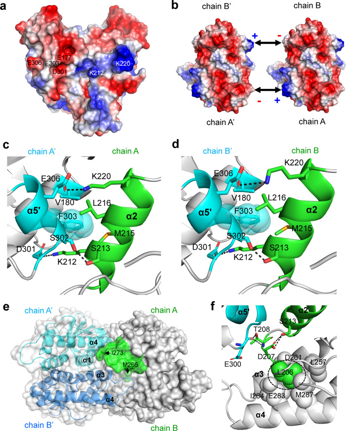
Fig. 6. The oligomerization mechanism of PcSTING revealed by crystal packing.
a The electrostatic potential surface of a PcSTING dimer. The surfaces are colored in blue for positive potential (10 kcal/mol), red for negative (−10 kcal/mol), and white for neutral. The residues involved in electrostatic interaction and hydrophobic stacking are indicated. b Binding scheme of dimer–dimer interaction of PcSTING shows that the positively charged patch on one side is complementary to the negatively charged patch on the other side, constituting a basis for filament formation of bacterial STING. c, d Detailed view of the oligomerization interface between (c) chain A and chain A’ or (d) chain B and chain B’ of PcSTING. The chain A/B of the PcSTING dimers in (b). The interacting residues are shown as sticks. The H-bond and ionic bonds are indicated in black dashed lines. To emphasize the stacking interaction, the residue F303 is highlighted by showing its sphere model. e Surface representation of the PcSTING tetramer. The α3-α4 loop (green, residues 267–276) from chain A of one PcSTING dimer makes extensive hydrophobic interaction with α1 and α4 helix of chain A’ (cyan) and another α3-α4 loop of chain B’ (blue) of the adjacent PcSTING dimer. The side chains of M266 and I273 that participate in oligomerization are indicated by black arrows. f The predicted oligomerization interface (residues D119-S123) in FsSTING corresponds to the loop region before α2 helix in PcSTING. Hydrophobic-interacting residues are shown as spheres and hydrophilic interacting residues are shown as sticks. The conserved leucine residue (L206 in PcSTING) that was mutated to arginine and prevented the filament formation in SfSTING is highlighted by a black dashed circle. All the α helixes are labeled in bold fonts.

