Figure 2.
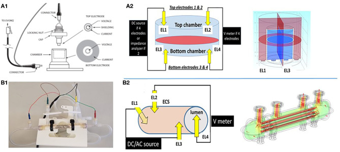
Schematic depiction of two different configurations used to grow cerebrovascular cells to mimic the blood–brain barrier. (A1,A2) shows a Transwell device and the settings used to measure TEER. Owing to its geometry and the placement of electrodes close to the monolayers, the control of voltage across the cell monolayer is uniform. This was modeled by the multiphysics model COMSOL (Version 4.3b) as shown in the upper right panel. In the 3D configuration (B1,B2), the control of voltage is also continuous owing to the four-electrode configuration used. Thus, two or four electrode systems have been used to measure impedance in vitro. We measured trans-endothelial electrical resistance under many different conditions and with several different electronic devices. However, when modeling the behavior of the two electrode configurations, we found that while this approach is reliable for 2D models, it fails to satisfactorily control voltage on a more sophisticated 3D model (Figure 3). Note that for the 2D model, the electrodes had a surface area comparable to the area of the layer across which resistance was measured, while for the 3D model imitating a blood vessel, the electrodes consisted of small point contacts. These are the contacts used for organs-on-a-chip, since complex geometries disallow coating the structure with large closely spaced electrode contacts. We propose to use a four-point, AC system (as in the DIV-BBB; see also Figure 3) to overcome this.

