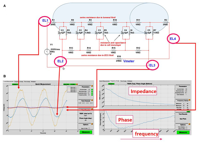
Figure 3.
(A) Equivalent circuit we used to predict the accuracy or measurements of transcellular resistance in different 3D organs-on-a-chip. For example, the shaded area in the figure represents the size of a venule (~200 μm diameter). In this model and with an AC, four-electrode clamp approach, the resistance measured is accurate. This is achieved by measuring the relative contribution of various resistive components and by subtracting background resistance from the total to obtain cell TEER. (B) Output of the DIV-BBB TEER software based with Matlab. Note the four waveforms measured at the electrodes EL1–EL4 in (A) and the impedance/phase diagram across a broad range of frequencies.

