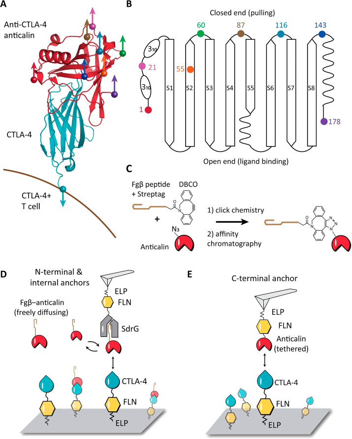
Figure 1.
Anchor point selection and AFM-SMFS measurement setups. (A) Structure of CTLA-4 in complex with anticalin (PDB code 3BX7). Anchor points on the anticalin are shown as colored spheres. The anchor point on CTLA-4 is fixed at the C-terminus, mimicking the natural tethering geometry on the cell surface. (B) Anticalin has a central β-barrel, consisting of eight antiparallel β-strands (S1–S8) connected by short flexible linkers. The anchor points shown as colored dots were chosen at the closed end of the β-barrel to avoid interference with the binding interface. (C) Bioorthogonal conjugation of a fibrinogen β (Fgβ) peptide to the anticalin. The residue at the selected anchor point was replaced by p-azido-phenylalanine using amber suppression to introduce an azide group. The azide was covalently linked with a synthetic peptide comprising Fgβ-StrepTag and a C-terminal DBCO group using click chemistry. (D) AFM measurement setup for testing N-terminal and internal anchor points with freely diffusing Fgβ-anticalin. Anticalin conjugated with Fgβ was added to the measurement buffer to a final concentration of 1 μM. SdrG-FLN-ELP-ybbr was immobilized on the AFM tip, and the ligand (CTLA-4-FLN-ELP-ybbr) was immobilized on the glass surface covalently via a ybbr tag. (E) AFM measurement setup with tethered anticalin for probing the C-terminal anticalin anchor point. Anticalin-FLN-ELP-ybbr was immobilized on the cantilever, and CTLA4-FLN-ELP-ybbr was immobilized on the glass surface.

