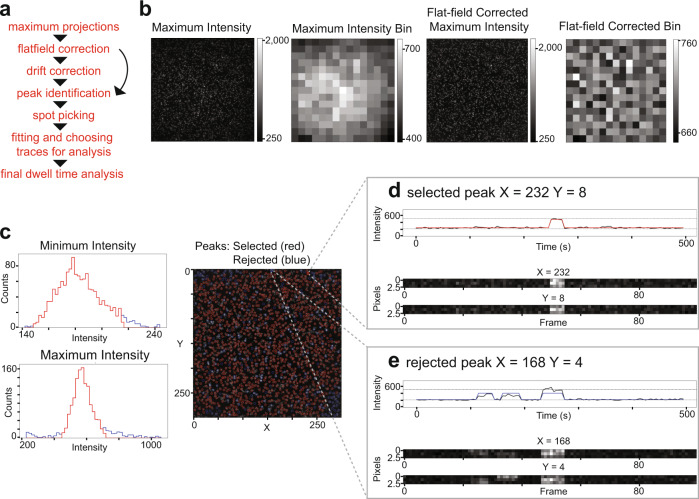
Fig. 3. SMOR analysis.
a Analysis pipeline for SMOR analysis. b For flat-field correction, the maximum intensity projection of a 300 × 300 pixel movie is binned into a 20 × 20 pixel grid, flat-field corrected, and then binned again to check correction. c Histograms of minimum and maximum intensity values along traces for each peak. Red indicates selected peaks (≤3 SD from median) and blue indicates rejected peaks. At right is a maximum intensity projection with selected (red circle) and rejected (blue circle) peaks (x, y coordinates). d Representative single-molecule trace of a selected peak at coordinates (232, 8). e Representative single-molecule trace of a rejected peak at coordinates (168, 4).

