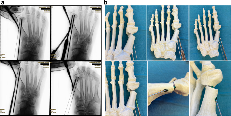
Fig. 11.
a Top left: the 2.0 mm K-wire is exchanged for the guidewire. Top right: Getting the correct length with the corresponding cannulated length gauge and crosschecking by placing the screw on top of the foot. Bottom left: Inserting the first screw and making sure not to bend the guidewire. Bottom right: The oblique view is key to determine the correct length, both proximally (screw head protrusion) as well as distally (intraarticular protrusion). Until the first screw has been safely established, the position of the lever is maintained to avoid secondary dislocation of the metatarsal head. b As described above, the corresponding steps to safely place the first screw are demonstrated in a saw bone model

