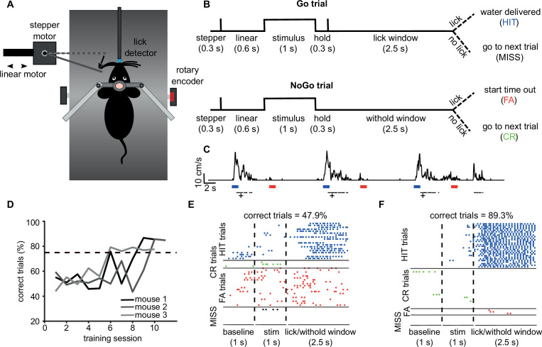
Figure 7. Vibrissae-based object localisation task.
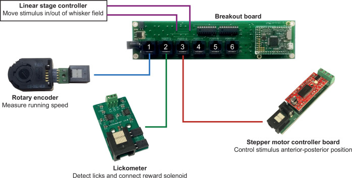
(A) Diagram of the behavioural setup. Head-fixed mice were positioned on a treadmill with their running speed monitored by a rotary encoder. A pole was moved into the whisker field by a linear motor, with the anterior-posterior location controlled using a stepper motor. Water rewards were delivered via a spout positioned in front of the animal and licks to the spout were detected using an electrical lickometer. (B) Trial structure: before stimulus presentation, the stepper motor moved into the trial position (anterior or posterior). Next, the linear motor translated the stepper motor and the attached pole close to the mouse’s whisker pad, starting the stimulation period. A lick window (during Go trials) or withhold window (during NoGo trials) started after the pole was withdrawn. FA, false alarm; CR, correct rejection. (C) pyControl simultaneously recorded running speed (top trace) and licks (black dots) of the animals, as well as controlling stimulus presentation (blue and red bars for Go and NoGo stimuli) and solenoid opening (black crosses). (D) Percentage of correct trials for three mice over the training period. Mice were considered expert on the task after reaching 75% correct trials (dotted line) and maintaining such performance for three consecutive days. (E) Detected licks before, during, and after tactile stimulation, during an early session before the mouse has learned the task, sorted by trial type: hit trials (blue), correct rejection trials (green), false alarm trials (red), and miss trials (black). Each row is a trial, each dot is a detected lick. Correct trials for this session were 47.9% of total trials. (F) As (E) but for data from the same mouse after reaching the learning threshold (correct trials = 89.3% of total trials).


