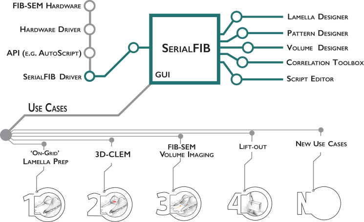
Figure 1. Software architecture, modules, and use cases of SerialFIB.
Developments presented in this work are highlighted in green. The graphical user interface (GUI) is largely decoupled from instrument operations, which are controlled by the developed SerialFIB driver. Modules (right) enable design of protocols for different use cases (bottom, 1–4), and a scripting interface that offers flexibility for new developments (bottom, N).


