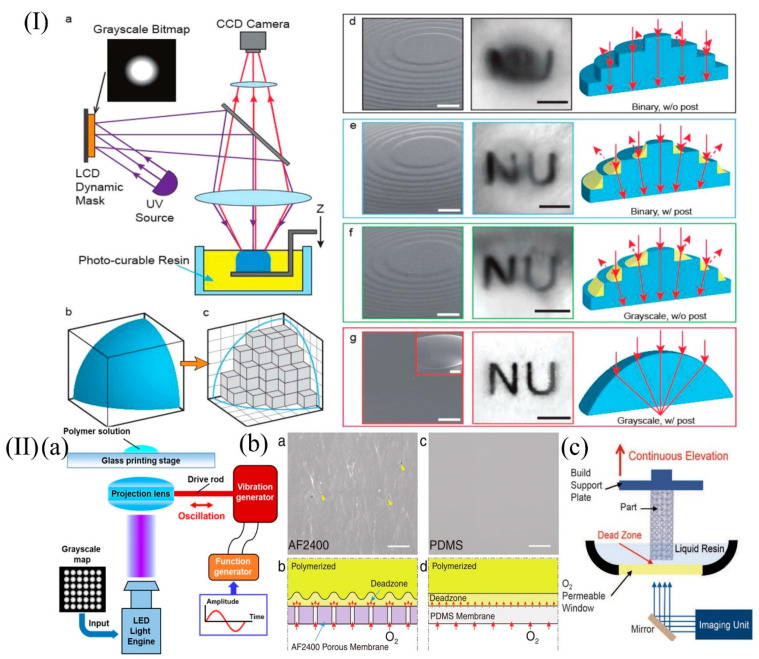
Figure 8.
(I) 3D printing of an optically smooth surface using the PμSL system and post-processing steps. Panel (a), schematic illustration of the PμSL system. A 3D solid model with smooth surfaces shown in panel (b) is approximated as a set of discrete voxels; results in the pixelated rough surface are shown in panel (c). Panels (d–g), progressive improvement of surface roughness and the resulting imaging characteristic of 3D-printed lenses using various methods. (II) (a) Schematic of the oscillation-assisted DLP-based printing system. (b) Magnified SEM image shows in panel (a), an AF2400 Teflon membrane with distinct surface texture and pores and in panel (c), a PDMS membrane with smooth surface. Panel (b), schematic diagram of the different dead zone interfaces formed through a porous Teflon membrane with nonuniform oxygen permeability and in panel (d), a PDMS membrane with uniform oxygen permeability. (I) Reprinted with permission from ref. [100]. (II) (a) Reprinted with permission from ref. [101]. (II) (b) Reprinted with permission from ref. [21]. (II) (c) Reprinted with permission from ref. [102].

