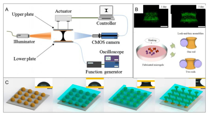
Figure 7.
(A) Schematic diagram of the liquid bridge. The movement of the upper plate is controlled by a pneumatic actuator, and the lower plate is fixed during the experiment so that the droplets remain stable until they come into contact with the upper plate. Then the light source creates a brightness difference between the liquid and gas regions to make the droplet boundary clearer. The initial droplet and the droplet-splitting process are captured by a complementary metal oxide semiconductor camera. (Reproduce with permission d from the Reference [36]). (B) Fluorescent images of live/dead staining of cells in hydrogel at t = 24 h and t = 72 h (green represents live cells and red represents dead cells) (top left corner); statistical results of cell viability (top-right corner); schematic diagram of directional assembly of dumbbell microgels and rod microgels (bottom-left corner); phase contrast image of two microgel components (bottom-right corner). (Reproduced with permission from the Reference [38]). (C) Flow chart of preparing a microgel module by using a liquid bridge phenomenon. At first, the base material is stuck onto the upper part of the lifting platform with double-sided tape. Next, the joint is loosened and the arm is moved until the upper plate is just parallel to the lower plate, which ensures that the two plates are parallel between the liquid bridge. The joint is fixed, another substrate is placed below, and a drop of gel precursor is placed on the substrate. Then, a liquid bridge is formed between the two bases by moving the arm. The knob is then adjusted so that the liquid bridge is stretched or compressed at a low speed to achieve the desired shape. (Reproduced with permission from the Reference [36]).

