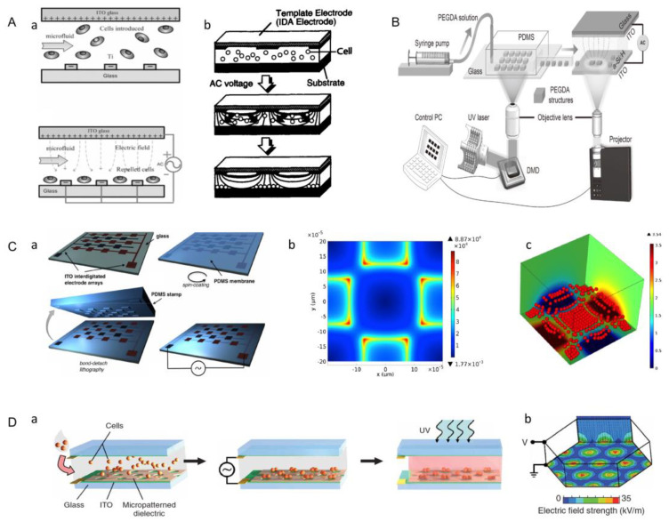
Figure 16.
(A) Working principle of liver cell graphics chip. (a) A side view of a spatially randomly distributed cell (up) and side view of cell distribution under n-DEP. Hepatocytes are injected into the microfluidic cavity with continuous flow input and randomly distributed along the flow direction. (b) When sufficient alternating current (AC) is applied, the randomly distributed cells are repelled by the n-DEP effect under the control of the balancing force generated by DEP and fluid dynamics, and are arranged between the electrodes into the desired bead array pattern (Reproduced with permission from the Reference [84]). (B) Schematic illustration of the high-throughput fabrication and flexible manipulation system. The system consists of two main components: a DMD-based hydrogel manufacturing system for on-demand manufacturing; an ODEP force-based operation and assembly system for precise control. (Reproduced with permission from the Reference [45]). (C) (a) Schematic diagram of a quadrupole electrode array device. (b) Distribution of electric field intensity. (c) The aggregation of cells. (Reproduced with permission from the Reference [125]). (D) (a) The photosensitive prepolymer solution containing cells was filled between two conductive indium tin oxide (ITO)-coated plates. An insulating photoepoxy resin (SU-8) mask was placed on the bottom electrode plate. The insulating area covered most of the conductive surface, forming electrodes in the non-insulating area. An AC voltage was applied to the top and bottom plates, producing a spatially non-uniform electric field. (b) Distribution diagram of electric field intensity. (Reproduced with permission from the Reference [126]).

