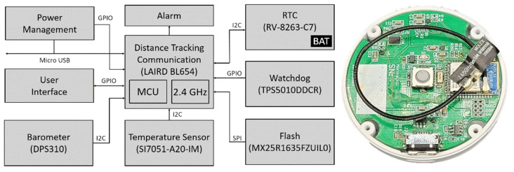
Figure 4.
Tracking device block diagram and realized printed circuit board (PCB): Power management—integrated circuit (IC) responsible for charging the battery and maintaining a stable supply of voltage for the microcontroller unit (MCU) and other circuit logic; Alarm—RGB LED signalization; RTC—time recorder; Watchdog—component for resetting the system in case of MCU error; Barometer—atmospheric pressure monitoring; Temperature sensor—wrist temperature monitoring; Flash—long-term non-volatile storage for the MCU; User Interface—buzzer and button to communicate status, battery level, and syncing operation to the user; LAIRD BL654—main MCU used to control the connected components and direct operations of the device.

