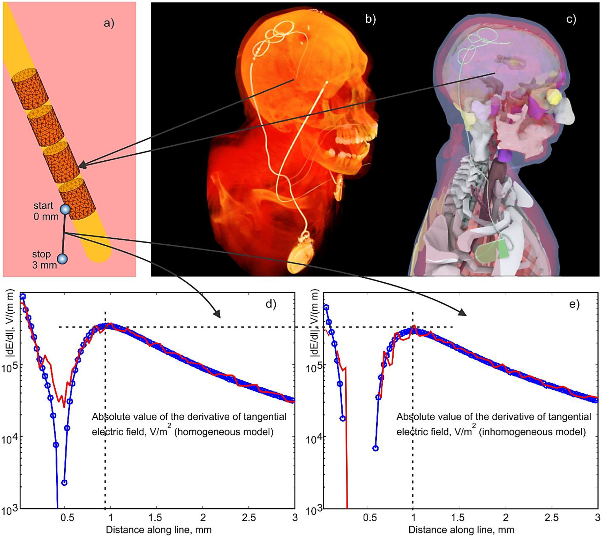
Fig. 6.

a) – BEM-FMM Electrode mesh assembly around insulating urethane lead. Active electrode is assigned –1 V vs IPG (held at zero voltage), and no specific voltage is assigned to other electrodes (floating condition). b) –CT of insulating lead/IPG with the electrodes; the second electrode relates to another device. c,d) – IPG Device with the lead and electrodes embedded into the CAD model; d,e) – magnitude of the derivative of the tangential electric field, dE/dl (the second derivative of the electric potential), along a small fraction of the polyline with the length of 3 mm shown in Fig. 6a which starts in the middle of the active electrode held at –1 V for homogeneous (d) and inhomogeneous (e) head/torso model, respectively. Ansys Maxwell FEM solution is marked red; BEM-FMM solution is marked blue.
